Hello Tello Pilot!
Join our DJI Tello community & remove this banner.
Sign up

Mi Repeater 2 moded

@Stele,

Contratulations for your succesfull test, but not a very impressive distance ;)

Talking about video settings, as you can read here New app: TelloFPV that @volate!lo says their favorite settings are
"focused to get decent video over a reasonably stable wifi link"

For pure FPV long distance with stable video stream and no matter video quality you should test shorter IFrame period and lower bitrate.

My favorite settings nowadays: Bitrate AUTO, iFrame interval: 1 second and Stream Recovery ON

All the best.

tellofvp.jpg
 
Last edited:
  • Like
Reactions: Stele
Thank you @raulvolador .
As I mentioned that wasn't even the max distance for my setup. I just didn't want to risk losing the tello.
Will do more tests with the settings you mentioned. But atm. It's really windy here...:(
 
For really long distance use 1Mbit bitrate and 1 sec IFrame interval. That will give you a steady but blurry low detail stream
Will try that. But the main goal is to extend the range in which I can fly with 4mbit bit rate and a steady link.
 
  • Like
Reactions: xcrost
I've tinkered even more and build a set of antennas.
View attachment 2599
They are called moxon antenna and are directional ( round about 90-120 degrees)
Once again I can't test outside but the inside test are very good.


There are a couple of things you need to take into consideration with your design. I am not trying to criticize your attempts in any way only want to help.

1. You have positioned your antennas with a horizontal polarity. Not sure what the best polarity would be but I think the Tello is vertically polarized. The repeater's antenna is vertically polarized.
2. Your driven element is facing down and the reflector element is reflecting the RF energy down towards the ground not towards the drone.
3. The driven element should point the desired direction (towards the drone) with the reflector behind. The reflector element is placed in such a way so as to redirect the RF energy coming off the driven element going in the undesired direction back froward in the desired direction. This is what gives this antenna gain over a simple dipole antenna.
4. Wood is a terrible sub-straight to use as it is very lossy at 2.4 GHz. A lot of the RF energy is being absorbed and lost in the wood. It will also change the impedance of the antenna away from the desired 50 ohms. Your printed frame should be better. Take your printed holder and place it (plastic only no antenna wire) in the microwave for a couple of minutes. If the plastic gets warm (absorbing energy) it is not a good material to use. If it remains cool would be a great material to use. Free space (no sub-straight) is the best.


1547584467595.png

The illustration shows the a vertical driven element in front of the reflector in a vertical plane. If you rotate the antenna 90 degrees it will then be in a horizontal plane. Both planes should be tested for best signal level.

I believe when measuring the signal strength a lower number is a better stronger signal. Even if you are looking at signal to noise. Lets assume the receivers threshold is somewhere around -100 dBm then a measured signal of -90 would be 10 db above the noise. A signal of -70 dB would be 30 dB above the noise. In any case using the WiFi signal analyzer in your phone will be your best tool for determining actual gain. When making your measurements be sure to rotate the phone 90 degrees and get a measurement in both the horizontal and vertical polarization as we are not sure what plane the antenna in the phone might be.

You may want to experiment with only one antenna as spacing antennas for diversity is another problem all together. You can have 2 perfect antennas placed the wrong distance apart and totally screw up the antenna pattern.

I am looking forward to following your progress.

~Bill
 

Attachments

  • 1547582782709.png
    1547582782709.png
    26.6 KB · Views: 4
  • Like
Reactions: ph2t and Stele
There are a couple of things you need to take into consideration with your design. I am not trying to criticize your attempts in any way only want to help.

1. You have positioned your antennas with a horizontal polarity. Not sure what the best polarity would be but I think the Tello is vertically polarized. The repeater's antenna is vertically polarized.
2. Your driven element is facing down and the reflector element is reflecting the RF energy down towards the ground not towards the drone.
3. The driven element should point the desired direction (towards the drone) with the reflector behind. The reflector element is placed in such a way so as to redirect the RF energy coming off the driven element going in the undesired direction back froward in the desired direction. This is what gives this antenna gain over a simple dipole antenna.
4. Wood is a terrible sub-straight to use as it is very lossy at 2.4 GHz. A lot of the RF energy is being absorbed and lost in the wood. It will also change the impedance of the antenna away from the desired 50 ohms. Your printed frame should be better. Take your printed holder and place it (plastic only no antenna wire) in the microwave for a couple of minutes. If the plastic gets warm (absorbing energy) it is not a good material to use. If it remains cool would be a great material to use. Free space (no sub-straight) is the best.


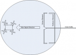
View attachment 2729

The illustration shows the a vertical driven element in front of the reflector in a vertical plane. If you rotate the antenna 90 degrees it will then be in a horizontal plane. Both planes should be tested for best signal level.

I believe when measuring the signal strength a lower number is a better stronger signal. Even if you are looking at signal to noise. Lets assume the receivers threshold is somewhere around -100 dBm then a measured signal of -90 would be 10 db above the noise. A signal of -70 dB would be 30 dB above the noise. In any case using the WiFi signal analyzer in your phone will be your best tool for determining actual gain. When making your measurements be sure to rotate the phone 90 degrees and get a measurement in both the horizontal and vertical polarization as we are not sure what plane the antenna in the phone might be.

You may want to experiment with only one antenna as spacing antennas for diversity is another problem all together. You can have 2 perfect antennas placed the wrong distance apart and totally screw up the antenna pattern.

I am looking forward to following your progress.

~Bill

Thanks man! I appreciate your detailed answer and I´m open to any sound input.
I´m by no means an expert (or even experienced^^) in the RF- and antenna-field. this moxon antennas are the first antennas I´ve ever build.
to 1. valid point will look in to that as soon as possible
to 2.and 3. that´s only on the photos. as you can see there is a hinge at the base of the antennas to point them as i want (the right way of course)
to 4. the wood antennas were just a prove of concept. The new printed ones are from ABS and should be fine (totally non organic)

I tought about spacing of the antennas to... is there any reliable source of information about that?

hopefully the weather will be gracious so I can perform a few more tests

regards Stele
 
Hi Stele,

There is lots of info about spacing for antennas. Do a google search "space diversity antenna separation" . Cisco has some white papers on the topic. If I were to guess I would start out at 1 wavelength. 12 .5 cm or 4.95 inches. Any odd multiple should be fine.

I have built several moxon antennas over the years. They are great antennas. unfortunately I have never stacked them for gain or diversity. So I am not sure what pattern to expect. Point them in the same direction not at any angle to each other. You are only trying to fill any path nulls not trying to increase the gain.

~Bill
 
  • Like
Reactions: Stele
Thanks again @bmelody
I´ll definitely look into that.
And so we have 3 potential flaws in my first setup:
- Horizontal vs. vertical polarization
- Antenna spacing
- of course i´ve aligned them at an angle to one another to "cover more area" (totally forgot that they are sending too^^)

should be a few quick modifications before I can test again.
 
Hey Stele,

Here is the drawing I attempted to sent to you.

When the polarization is vertical the antennas are side by side

When the antennas are horizontal they are one on top of each other.

1547752645627.png

~Bill
 
  • Like
Reactions: volate!lo and Stele
Thank you @bmelody for your expertise.
I've designed two more antenna prototypes for further testing.
Both have improved measurement details (quality of life things) as well as a redesigned cable mount to accommodate HF-antennacable (RF240).
The first one is a set of independent antennas to see if there is any benefit in polarisation or in Politik them in a V shape.
received_481645785692990.png

Second on is a pair of antennas fixed parallel to one another and with a distance of 12.5cm.
received_805632009786512.png

I'll print them over the weekend and hopefully have them done soon.
 
Next range test with the old moxon antennas.
1mbps and 1s iframes
Got to almost 300m.
Screenshot_20190118-143316_TelloFPV.jpg
 
All,

After looking at the antennas in the Tello they are vertically polarized. Also a very interesting but terribly inefficient design. But due to limited space it is the best that can be done.

I can gain 20dB (measured using the TelloFPV app) by simply holding my phone in a vertical (portrait) position. And yes, the readings in the TelloFPV app are RSSI (receive signal strength indicator) so the higher it reads the stronger the signal.

Stele's moxon antenna design should provide greater distance however you would have to keep the antennas pointed directly at the bird. Moxon antennas are directional that is how they get the gain

raulvalador's design may end up with less range but would you would not have to bother with pointing antennas using his omni-directional design.

With either design placing the unit up high will also increase the range.

Here is another idea that would be fun to play with. Modify the phone or tablet and bring out the WiFi antenna connection using coax cable. Then connect that cable it to an external 2.4 GHz bi-directional amplifier with antenna. This will increase the control range by a huge amount but the video signal coming back from the bird will not be much better than using a repeater due to the low power transmitter in the Tello. Here is a link to such a device.

EDUP 2.4Ghz 4W Wireless Wifi Power Booster Signal Amplifier Wi-Fi Range Extender 723172893415 | eBay

If one was to modify their phone or tablet and connect it to an external 6 dBi gain antenna it would be as good as using a repeater. The phone or tablet may also have 2 internal antennas for diversity. If this is the case even better. Bring out both antenna connections and use 2 external antennas.

Too many projects....Too little time

What ever you do.... Have fun doing it!
 
@bmelody
Here is another idea that would be fun to play with. Modify the phone or tablet and bring out the WiFi antenna connection using coax cable. Then connect that cable it to an external 2.4 GHz bi-directional amplifier with antenna. This will increase the control range by a huge amount but the video signal coming back from the bird will not be much better than using a repeater due to the low power transmitter in the Tello. Here is a link to such a device.

EDUP 2.4Ghz 4W Wireless Wifi Power Booster Signal Amplifier Wi-Fi Range Extender 723172893415 | eBay

If one was to modify their phone or tablet and connect it to an external 6 dBi gain antenna it would be as good as using a repeater. The phone or tablet may also have 2 internal antennas for diversity. If this is the case even better. Bring out both antenna connections and use 2 external antennas.

I thought about using a booster too. because what is more fun than throwing brute force at a problem :cool::D
but that would be (at least in Germany) illegal. we are restricted on 100mW for 2.4 gHz...:(

after a recent test with my moxon setup and a near flyaway due to a drifting tello. i´ve decided to go omidirectional for now.
But with a twist. I´ll combine two different rod antennas, one low gain true omidirectional (coverage is like a sphere) and a high gain rod antenna (coverage is more like a donut). That should give me max. 360° range and coverage. I won´t brake any distance records with this setup but it´ll be good for relaxed flying.

To find out what kind of high gain antenna i´ll need i did a little bit of math and a drawing:p
let´s assume a 2dbi omnidirectional antenna gives you about 80m of "good" range. with the max. flight height of the Tello (30m) we can calculate the beam angle our high gain antenna must have. In this case 37°, so lets say 40°.
With that info I can use a 5-6dbi antenna as my second one.
antenna setup.jpg

That should give me the best possible 360° coverage and range possible without going up in transmission power or going directional.
 
Last edited:
Hi Stele,

Yes, use the 6 dBi gain antenna if possible. The beauty is, any gain in the antenna applies in both transmit and receive.
 
  • Like
Reactions: Stele
Next step done.
I've build a proper base for the repeater including a powerbank.
The antennas I choose are still in the mail... the ones on the photo are just some random ones I had laying around.
20190201_212150.jpg

You can still see the status led and push the reset button
20190201_212522.jpg

A switch for the repeater on one side
20190201_212351.jpg

And the powerbank terminals on the other
20190201_212429.jpg

That's what it looks from the inside
20190201_212303.jpg

Looking forward to get my antennas and do some tests.
 

New Posts

Members online

Forum statistics

Threads
5,690
Messages
39,934
Members
17,023
Latest member
Repiv

New Posts